 |
The Curta.org Bulletin Board Welcome to the Curta.org Information Exchange Forum for the Curta Enthusiast Community This forum is temporarily read-only. |
| Remaking a Curta Type 1 Rev 2 Goto page 1, 2 Next | |
| The Curta.org Bulletin Board Forum Index -> General Questions and Help | |
| Author | Message | ||||||
|---|---|---|---|---|---|---|---|
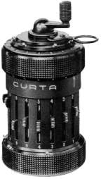
| thomasmanegiste Joined: 03 Mar 2025 Posts: 10 |  Posted: Tue Jul 22, 2025 6:28 pm Post subject: Remaking a Curta Type 1 Rev 2 Hello everyone, I'm sharing a projet I'm undertaking: remaking a curta. The genesis of this projet goes back a little. During the lockdown, I've discovered the curta via a youtube video (https://www.youtube.com/watch?v=loI1Kwed8Pk) A while later, I've made a tellurion (astronomic contraption that models positions of Sun, Earth and Moon). https://www.youtube.com/watch?v=tHdg_emv9bs https://drive.proton.me/urls/TZ1V4R16ZG#g7BRQ7PPiLVf After making this contraption, I've decided to start making a curta. At first glance, it seems extremely complicated, due to limited mechanical plays, clearances for oil films... I think this is doable (whithout questions of profit or time), because of the exceptionnal conception : each part is not so complicated. I think this conception was driven by the need to manufacture in high quantity, whithout numerical controlled machines. The goal of this project is to make a fully fonctionnal Curta Type 1 Rev 2, 1:1 scale. I'm using the original drawings, and I try to buy less tools as possible (I'm making my own special profile mills for gears). https://drive.proton.me/urls/SB7YSGAQ0C#kcmVdO47eQIq https://drive.proton.me/urls/X0C3ZZGXZW#xA09qFIgmE0t I'm currently working on the different gears : -Counters sliding gears (10038): https://drive.proton.me/urls/Y3787SAJSG#8pVBM7FVFdaA These are made out of .5mm sheet metal, then mounted on brass hub (10017, 10020 or 10032) -Frontal counter gears (10052): https://drive.proton.me/urls/42XP9E5F10#QZmRcWRIpsvt https://drive.proton.me/urls/7P567BTBQW#xakU6BPWJB0q -Counters rollers (10045): https://drive.proton.me/urls/WSQZHMMRSW#fpXsFju4ZocH For those parts, I'm planning to use shrink fit workholding fixture to machine the gear. This project is progressing slowly, as I don't have much time to devote in it (studies etc...). Let me know if you want regular updates or a deeper view of the machining processes. One last word: the goal is not to have a 100% conform replica. I'm adjusting the original conception to the available materials, for example the tolerances are varying from the original. I'm also planning to add some interesting features, such as the Silent Curta spring, that weren't implemented on Type 1 Curtas. Have a nice day, Thomas. | ||||||
| murff Joined: 27 Oct 2009 Posts: 620 | Posted: Wed Jul 23, 2025 3:07 pm What an exciting project! Which variant do you want to build? I hope an all-metal version... should it succeed - do you want to produce a small series? I would like to preorder serial number 0002! How do I get access to the documents? Do I need an account? (update - I just created an account... interesting pictures!) I would love to get regular updates on your work!  I wish you good luck and much success! | ||||||
| Kmcqueen Joined: 14 Apr 2023 Posts: 38 | Posted: Wed Jul 23, 2025 5:10 pm I would be interested also - Let me know what to do get access to your photos. I've been trying to picture the process for cutting that spiral groove into the setting shaft for years (without using CNC). I'll be curious to see how you pull that off. | ||||||
| thomasmanegiste Joined: 03 Mar 2025 Posts: 10 | Posted: Fri Jul 25, 2025 9:24 am Hello everyone !
I'm buiding two versions: one all metal, and one with an acrylic outside to see the guts. I would like to build a serie of curtas, but there are several problems : -Price : because I can't produce in big quantities, the price will be extremely high. I might sell whithout profit, just for fun, but it will probabely be a thousand at least. -Technical industrialisation difficuties : to be able to produce several machines, I need to invest in CNC machines (swiss turning center, 3 axis mill), and to rethink my whole process to be more effective. Depending on how many people want one, I might explore possibilities of serial production. If not, I might make one more for you 
The principle is to link a linear move (X), with a rotary move (using a rotary table). It might be a little headache, as I don't have a universal rotary table, but it is still possible with a few gears and modifications of my conventionnal mill. https://youtu.be/uaJsgsLkwQg Example for manufacturing a counterboring mill.
Let's try this: [img] https://drive.proton.me/urls/PDTXGCC7MW#BaQEmzgNdeQH [/img] Tell me if you can see this one. If not, can someone explain me how I should put images? I'm using the img and /img tags. Have a good day! | ||||||
| murff Joined: 27 Oct 2009 Posts: 620 | Posted: Fri Jul 25, 2025 10:33 am
OK - I'm there! The early bird price is right  An acrylic case for the Curta series would be cool! I'm sure a lot of people would be interested in that... ... the historical model: https://digital.deutsches-museum.de/de/digital-catalogue/collection-object/78037/ PS: The image tags work perfectly - you need to make sure the image source is freely accessible | ||||||
| thomasmanegiste Joined: 03 Mar 2025 Posts: 10 | Posted: Fri Jul 25, 2025 12:37 pm @Kmcqueen I changed the way I put pictures in my posts. Let me know if it's working for you. | ||||||
| murff Joined: 27 Oct 2009 Posts: 620 | Posted: Fri Jul 25, 2025 1:02 pm no . . . between the two Img tages must be the url to a picture file like this: https://curta.li/pict/04_werbung/42_innova11.jpg  so you need an image host (or you have your own server...) | ||||||
| Kmcqueen Joined: 14 Apr 2023 Posts: 38 | Posted: Mon Jul 28, 2025 3:29 pm The new links work for me! Thanks! Also thanks for the machining video - makes complete sense now. I had originally looked at the grooves under magnification and though maybe they were made on a shaper.....but couldn't picture how to get the spiral twist. | ||||||
| thomasmanegiste Joined: 03 Mar 2025 Posts: 10 | Posted: Fri Aug 01, 2025 1:53 pm Hello everyone, Since the links are working now, I will resume posting. I know that the images should appear immediately, but the storage solution I use gives a link that doesn't end with .jpg or .png, so BBCode doesn't load the image. I'm working on a fix for that problem (making my website to load those images). Manufacturing of machine's frame: The frame is made of five parts: Top body (10011), lower body (10077) and three fastening columns (10064). Upper body: https://drive.proton.me/urls/C6CMN8Z2CC#1isjCX37VZMK https://drive.proton.me/urls/V48GDSH9H0#o16Azw5hV5wC The first OP is done on a DMG vertical 3 axis mill (no it's not mine, unfortunately). https://drive.proton.me/urls/MY0JXY2R9M#J66u6bCTgI0M I've only milled one of the radial slots (machining time was waaay too long, 1mm endmill, 0,002 mm/Z). This slot will be used to trim the part for OP 30. The frontal groves are machined with a 3mm endmill, with a ramping strategy. Little tip for Mastercam users: When using a contour ramping strategy with circular moves, don't forget to untick the option "linearize helixes". Otherwise you will machine a wonderful polyhedra instead of a cylinder. https://drive.proton.me/urls/CNC7PZEZS0#QZlAFXcYNIiy The reason lies in the Gcode analysis: Whithout this option, the gcode will look like this (using Siemens): G2 X4 Y0 Z-1 G2 X-4 Y0 Z-2 Each line programms one half turn of an helix (180°), while slowly going down. With this option ticked, the helix will be created as a sum of small discreet moves. Anyway. The lower portion is machines with two OP : one lathing OP (unfortunately I didn't take pictures), to machine the Ø33 bore, the part being held with a collet chuck gripping on the Ø8g6. Lastly, one drilling OP. The part is trimmed using gage blocks, slid in the radial slot. https://drive.proton.me/urls/T2CG07E5Q8#DBdiGUYnvjah I still have to machine the rest of the radial slots. Lower body: [url[https://drive.proton.me/urls/03D02BB2BC#bUdIUDdUNNmt[/url] This part is machined in two lathing OP, and a looong drilling one. https://drive.proton.me/urls/TCQJK015SM#QbGW1vZAx3ye https://drive.proton.me/urls/B4TH1XGGTR#WaERKb9RfaYo This part is not a big challenge, you just have to stay focused while drilling the holes. Fastening columns : https://drive.proton.me/urls/DZ89F9ESS4#kET05uREBtsz At first glance, this part seems easy. Until you realize that the parts must be drawn according to the small table at the bottom right, meaning that for a single production run, a batch of three parts must be within the same hundredth of a tolerance on the length 36.75. I have defined the following machining protocol (I do not have a spindle stop): -Machining of the first end -Turning over and rough cutting to length -Disassembly and measurement Then, I machine it to length using an industrial camera to rezero the lathe on the machined end face. https://drive.proton.me/urls/3QETH97SWR#N9kfhKqi8u7v Lastly, a bit of threading. https://drive.proton.me/urls/H2D1QMMXC0#9CpjOyC6psCA That's it! | ||||||
| murff Joined: 27 Oct 2009 Posts: 620 | Posted: Fri Aug 01, 2025 4:06 pm Thanks for the update... You seem to be really getting started! A question about the materials - you don't seem to always use the same metals - it certainly doesn't matter for the support columne - but I've read that Herzstark paid close attention to the choice of metals used, which is one reason why the Curta is so durable. I'm looking forward to seeing your step drum... that was a tough nut to crack for Herzstark!  | ||||||
| thomasmanegiste Joined: 03 Mar 2025 Posts: 10 | Posted: Sat Aug 02, 2025 7:45 am Hello hello,
I try to be as close as possible to the materials used. The lower body and the top body are made out of 2017 aluminum. This is a close match with "decoltal". The 2017 has 4% copper, as the decoltal has 6%. The upper body should have been made out of "anticorodal b" or 6082, aeronautic grade, corrosion proof aluminum. But I only had 2017 on hand. The yield strength are nearly the same (20 MPa of difference). I guess the choice was made because of the corrosion proof properties. I guess I will have to cover it in oil to stop corrosion  The columns are made out of bar turning brass, which is close (if not the same) as the "Messing 58 Pb" (modern equivalent MS58 brass). Last week's job : manufacturing a gear cutting endmill, in order to machine the counter rollers. The defitinion drawing includes the gear section dimensions, so I will start with those. https://drive.proton.me/urls/ZCHNXX139M#5g0uGWKi4m3T I soon have a 3D model of the endmill. https://drive.proton.me/urls/DTT82DT7PM#AdmS9onHVvMR The funny part is to define reliefs of the teeth's profile. Next, I create a set of drawings to machine the part. https://drive.proton.me/urls/E23G6K5FRG#ggKsmZ5AcKV6 https://drive.proton.me/urls/W510DK7FHR#zNvJacWgqpxb We start machining by turning the endmill, then by checking the thickness of the tooth section. https://drive.proton.me/urls/2MKYNH4C4M#9E203mTKmZBy https://drive.proton.me/urls/A329QNMSXW#lPZ50CGxU31b The indicator said 2.015 for 2mm, I will be fine. Then, milling. I'm using a "turn milling" strategy (which is just a modern way of saying "making a turning profile by milling"), that has the only pro to let me use a 3mm endmill that will create the 1.5mm radius I need. https://drive.proton.me/urls/CKAXX5M6C4#Cihc03c6crVn Little issue : I went too far and cut a bit of the neck of the mill (that is now 2.49 instead of 3). The radial flat is a tiny bi smaller, which means that the tooth's base flat will be too small. I don't have any way to measure this with a contact intrument, but I can take a high magnification picture and use gimp to measure the flat. https://drive.proton.me/urls/FASQ945KA8#lcEWqZjyWkXf https://drive.proton.me/urls/S3AGYHTC7C#Xldnq4CanIeg I then remove a little material on the outside diameter. https://drive.proton.me/urls/F0KHZQW0JG#SZOCq1woGhRq By fiming the machining operation, you can see currents in the oil dropplet that is atop of the part. https://drive.proton.me/urls/BNDYG18QB8#Eu9UDbDxYvv6 I's now time to mill the teeth and the relief. Teeth are no big deal. Make one, turn 90°, rince and repeat. https://drive.proton.me/urls/3CJD6HFVYR#mcYdSGWbbX9o Radial relief is also easy. It' s the profile's relief that is fun. I start by decentering the part in the 4-jaws-chuck., to the side I want to relieve (0.3mm). I turn the rotary table so that the cutting face is normal to the endmill's axis. I position the endmill as I did to make the profile, then I sweep the rotary table no about 30°, whithout cutting the next tooth. The decentered move means that th endmill is just touching the profile near the cutting face, but engages more and more as I turn. I don't have any meaninful pictures of that (pictures are meaningless). Tell me if this was understandable, if not I will make a 3D drawing of this. Lastly, quenching. https://drive.proton.me/urls/FS5D2TF088#yhbdWwDYRAN0 https://drive.proton.me/urls/VA74WRZVEC#qvmD5efe2vqH I'm making test cuts this moning, I will post results quickly. Have a nice day! Next week, if I have the time, we will discuss shrink fit, metrology and SPC. | ||||||
| thomasmanegiste Joined: 03 Mar 2025 Posts: 10 | Posted: Sun Aug 03, 2025 4:33 pm Hello everyone, I didn't have enough time this week-end to make tests for a shrink-fit workholding fixture. I worked on retrofitting a CNC 2 axis lathe, and on indicators maintenance. https://drive.proton.me/urls/2RBSZ6R8Q8#dIZVoMzhQTVs https://drive.proton.me/urls/6DVCVG3D6C#FSUfbBomYjlb First picture : two 1µm Millimess indicators unmounted. Second picture : a 0.5µm Supramess indicator. Those indicators will be used to check the 2mm bores on the 10043 counter rollers, equiped with a Mahr Marameter 844K system. I did machine a first test part to check the mill : I turned two 4.8mm cylinders separed by a 2.6mm turned section to simulate gear blanks. Holding the stock in a rotary table, I milled 10 teeth and performed the measurement given on the part's drawing. https://drive.proton.me/urls/ZCHNXX139M#5g0uGWKi4m3T Using two 1.5mm drill bits, I measured something 0.3mm away from the theorical value. My correction was too small. I took a 0.15mm cut, that lightly touched the 2.6mm diameter, but nothing dramatic. https://drive.proton.me/urls/7WQRBZZS3W#tAznkeLkWKUV On this picture it looks like it's a big cut. In fact, the cits on the small diameter are 0.2 by 0.2mm. After cutting the two apart, I can test the gears. https://drive.proton.me/urls/Q27X24QQ60#KsOicOaQOZJJ The center distance seems to be allright. Have a nice week! | ||||||
| thomasmanegiste Joined: 03 Mar 2025 Posts: 10 | Posted: Fri Sep 12, 2025 9:15 am Hello everyone, Little update : I finished retrofitting tne cnc lathe. I made a custom multi-tool holder while I was modifying the machine. Bottom to top : 2mm reamer, 1.9mm drill, point drill, external grooving tool. https://drive.proton.me/urls/4SMTHD23G4#Jm5eqabt41AO The indicators are fully serviced, I used one to check the bore of the 10043 counter rollers. https://drive.proton.me/urls/YE0S8S1R10#3UcW07PE7HcG I had a problem reaming those parts : whatever the settings, the bore was always conical and oversized. I ended drilling the part on the lathe and reaming it on a press drill. https://drive.proton.me/urls/S3Q2K6NX40#XeENyu3vBEwH Then, I milled the teeth. I don't have pictures of this operation, I will take some while making the second type of rollers (10045). One important thing : The undersized mill made the single-pass machining impossible. By going deeper, the cutting forces deformed the bore (there is only 4/10mm around the bore. By going 2/10 deeper, the material bent to the inside). I changed the process and made two passes (left and right side of the teeth), with a 6° offset. Counter body (10040): https://drive.proton.me/urls/GEZPYQJMJR#L6ZpUq19dkH2 This part is the first I modified to simplify the machining and assembly process (a curta 1 V3 if you will). This part is used to mount the counter's axles, and to offset the carriage by power of ten. In order to offset the carriage, the machine uses a pin, mounted in the machine's body, engaging in slots. But since some axles are for calculations, and others for rev counter, there are two pins, blocking the carriage from going down on a wrong position. Some of the slots are covered with a steel part. Some problems : -It is difficult to machine precise 2mm wide by 4mm deep groves. It will be way easier to mount axles in bores. Also, this solution will need one screw per axle, instead of two. -I need to make the steel part : https://drive.proton.me/urls/4BM4JJE0FW#dhX5g3EdgcZM Here also, it will be difficult to machine the grooves, even more difficult since the stock is thin. If we explore the different versions of the curta, we can see that this assembly evolved : https://drive.proton.me/urls/XRQ11AEG14#fk7umRi5tt2c Here is one of the last version of this part. We can see that axles are pressed into bores (H7 - p7), and that shallower grooves are used to index the carriage. The remaining question is : do we really need those grooves? We might use bores, that are easier to machine that grooves. <<warning : isostatism theory incoming>> The carriage is guided onto the machine's frame with a long centering - locating system (the pin is cylindrical, but the fact that it indexes into a groove means that it removes 1 Degree of Freedom and not two). Using a cylindrical pin and a bore would create a overconstrained mechanism, resulting in mechanical problems. We can use a pin in the two following cases: -If the machining accuracy is so high that the pin and bore axles are less than 1/2 of the mechanical play of the pin/bore assembly apart (5 microns or something approaching), resulting in complicated machining. -If the pin used has a diamond shape, making the axles distance non-critical. THe result are a less complicated machining process, and a lower price part. Consideering this, I redesigned the part using bores. One more benefit : the steel part is not needed anymore. The part is made in one turning and three drilling/reaming OPs. https://drive.proton.me/urls/NQJ3JHBGEW#1YqXQ4Hkj2qF https://drive.proton.me/urls/K4D287E568#RCXa74ZyHmJT https://drive.proton.me/urls/GKVDMZC824#XVMUukAh1XPP After mounting several axles : https://drive.proton.me/urls/A7ARTRF5M8#jCP7hhM1SpPe Frontal gears (10038): I talked about this part in my first post, it's a 5 teeth frontal gear. I made a first test with a STUB tool (STUB is a tool steel alloy), and it seems that the moron that made the tool forgot the side relief 🤡. When machining, the tool deformed (not quenched hard enough, I should have broke), making too big teeth. I made a second tool out of high-speed-steel that performed well. Again, I don't have any pictures. I will take some when making all axis. https://drive.proton.me/urls/D8GKCXDCHW#9Cio1Fhv3kId At this point, we finally can make 1+1=2 (being a little imaginative, the rollers are not engraved). By turning the 3D printed gear sectors, it drives the whole gear train, indexing the roller. https://drive.proton.me/urls/N0RPNA68YG#zayG2NUU1F3m Next big jobs : the carrying system, and zeroing system. Have a nice day! | ||||||
| murff Joined: 27 Oct 2009 Posts: 620 | Posted: Sat Sep 13, 2025 11:59 am Thank you very much for this latest update on your work on the new Curta! I hope I'm not the only enthusiastic viewer... 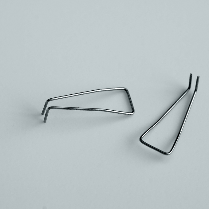 So many parts... | ||||||
| Kmcqueen Joined: 14 Apr 2023 Posts: 38 | Posted: Mon Sep 15, 2025 5:56 pm Thanks - always interesting to see process pictures. I've already learned a lot by watching your part holding techniques. | ||||||
| All times are GMT | Goto page 1, 2 Next |
Read-only archive of a phpBB 2 board · Powered by phpBB © 2001, 2005 phpBB Group